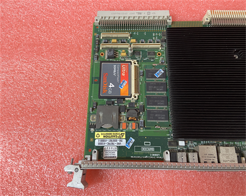
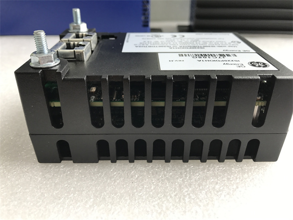
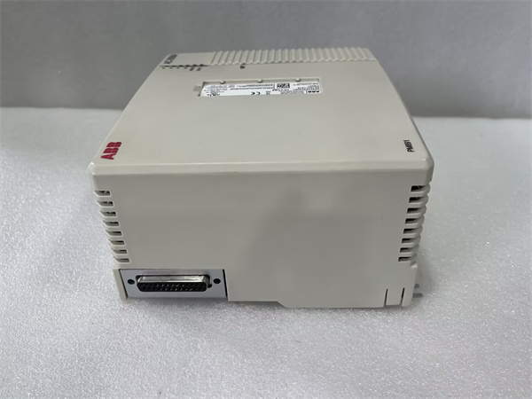
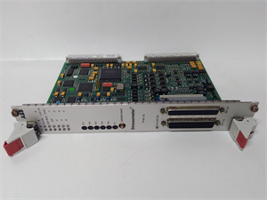
GE VME-7807RC VME-7
GE VME-7807RC VME-7 Production Description
Based on the available information and the understanding that VME refers to the VMEbus (Versa Module Eurocard bus), here's a possible breakdown of the production process for the GE VME-7807RC VME-7 board:
Components:
- High-quality electronic components suitable for a VMEbus environment:
- Specialized co-processors for specific tasks (e.g., graphics processing, signal processing).
- Input/Output (I/O) circuitry for interfacing with external devices (e.g., sensors, actuators) depending on the board's design.
- Communication interface chips for protocols other than VMEbus (e.g., Ethernet, serial).
- High-performance processor(s) or microcontroller(s) depending on the intended functionality of the board (e.g., data acquisition, signal processing).
- Memory chips for storing program code, data, and temporary calculations.
- VMEbus interface circuitry to enable communication and resource sharing within the VMEbus system.
- Additional functionalities might involve:
- Heat sinks or fans for thermal management, especially for high-performance processors.
Production Stages:
Component Sourcing:
- GE sources high-quality electronic components from reliable suppliers that meet the performance and reliability standards required for VMEbus applications.
PCB (Printed Circuit Board) Manufacturing:
- The VME-7807RC VME-7 likely utilizes a complex multi-layer PCB design to accommodate high-speed signals, power distribution, and proper signal integrity within the VMEbus environment. This PCB is likely fabricated according to GE's design by a specialized PCB manufacturer.
PCB Assembly:
- Automated pick-and-place machines for accurate component placement.
- Reflow ovens or wave soldering techniques for secure connections, likely with a focus on high-speed signal integrity.
- Additional hand soldering or rework for critical components (possible depending on the design).
- Automated and visual inspection to verify component placement, solder quality, and functionality.
- In a controlled environment with stringent quality control procedures, the electronic components are precisely placed and soldered onto the PCB. This might involve:
Programming and Testing:
- Electrical testing to verify signal integrity, power distribution, and functionality of the VMEbus interface.
- Performance testing to assess processing speed, memory access times, and data transfer rates within the VMEbus system.
- Functional testing to verify the board's ability to interact with other VMEbus modules and perform its intended operations.
- Environmental testing to verify the module's performance within its specified operating temperature, humidity, and vibration ranges.
- The PCB likely undergoes programming to define its functionality and communication protocols for VMEbus and potentially other interfaces.
- Rigorous testing is performed to ensure proper functionality, including:
Final Assembly and Packaging:
- The completed PCB is placed in its designated VMEbus form factor compatible housing. This ensures proper mechanical and electrical integration within a VMEbus system.
- The final assembly undergoes a final round of inspection for functionality, safety compliance, and cosmetic defects.
- Secure packaging is used to protect the board during transportation and storage.
Documentation:
- User manuals with clear instructions for safe installation, configuration, programming (if applicable), and operation within a VMEbus system.
- Technical specifications detailing the board's functionality, VMEbus compliance information, performance characteristics, environmental limitations, and any specific programming requirements.
- GE likely provides comprehensive documentation for the VME-7807RC VME-7, including:
Additional Notes:
- The specific production process might vary depending on the exact functionality and revision of the VME-7807RC VME-7 board.
- GE likely has a robust quality management system in place to ensure the reliability and performance of their VMEbus products.

